B/SOS Displays
[this write-up is from 2020 — my display code now supports 7-digits and has an adjustable refresh speed]
The games I’ve worked on have five 6-digit displays. There are four player displays and one for credits/ball-in-play. These displays only show one digit at a time, but they flip so quickly between them that it looks like all six are on at once. This is what the 320 Hz interrupt is for. Every 3.125 mS (320 Hz) another digit is shown.
Each time the interrupt service routine is called, the following steps are executed:
Displays are blanked (by turning off U10:CA2)
For each display:Digit select lines are set (digit 1-6), U11A:PA1-PA7
Current digit is put on data lines, U10A:PA4-PA7
Latch is strobed to lock the data into the current display (1-5), U10A:PA0-PA3, and U11A:PA0
Displays are un-blanked (by turning on U10:CA2)
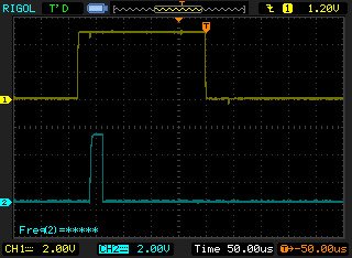
Here’s a picture of the signals generate by the original code (running on the M6800). In blue (mostly obscured by the white line for the frequency measurement), you can see the interrupt signal from the 555 timer. In yellow, you’ll see the blanking signal being sent out on U10:CA2 to blank all displays.

The entire blanking sequence takes about 240µS in the original code. The clock cycle is about 2µS, so it takes roughly 120 clock cycles to write all the displays. Here is the blanking signal expanded and each of the display writes shown during the course of one blank:


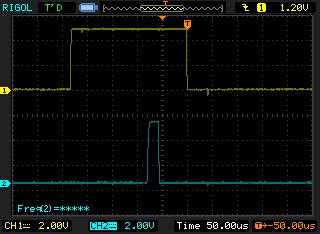
Right now you might be wondering why it looks like the display 5 latch overlaps the display 4 latch. I wish I knew! It takes a bit longer to latch display 5 because the latch line comes from U11A:PA0, and the value must be read, OR’d, and then written. With the other lines, they’re just the low order bits of the same byte that contains the BCD data. So, I get why it’s slower than writing displays 1-4, but I’m not clear on why it appears to overlap. I don’t have a picture of latch 4 versus latch 5. If I get one, I’ll update this.
So, by the end of the blanking signal, the processor has written data to each of the five displays. The digit is then incremented so the next time in the ISR, the next digit will be written. After it writes the last digit, it loops back around to the first.
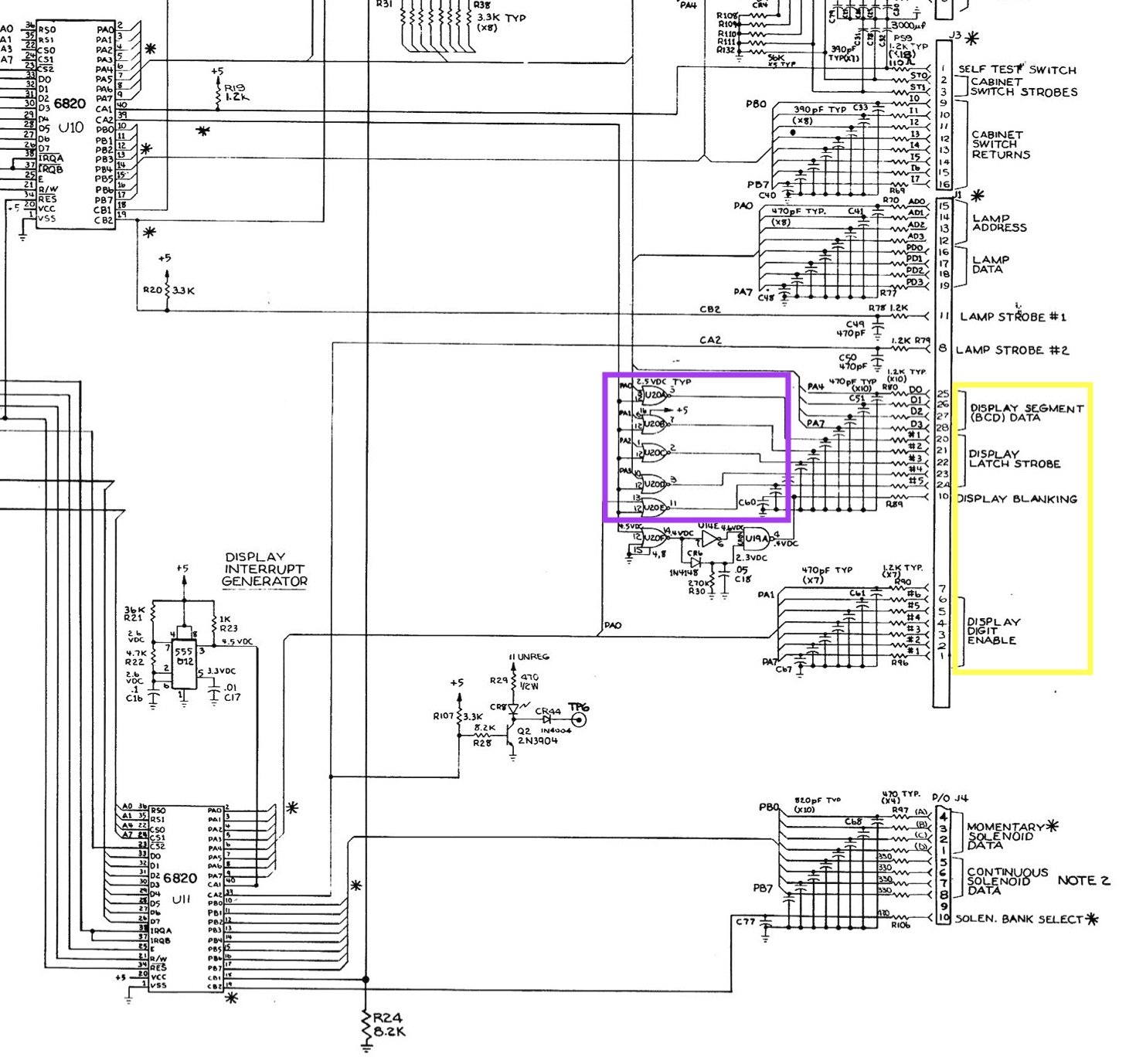
In the circuit diagram (above), check out the part that I put a purple box around. Those are the five lines that strobe the latches on the displays (U10A:PA0-PA3 & U11A:PA0). If one of those lines go low, one of the 6-digit displays will be latched to the digit enabled by the Display Digit Enable lines. That’s a problem because this interrupt is the most-frequent thing that happens and the lines of U10A are used for other things, like sending the lamp data and enabling the switch banks.
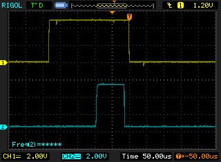
The solution is the U10:CA2 line. It’s the one that we’re using for display blanking, but you can also see that it’s NOR’d with each of the latch lines. Any time that U10:CA2 is high, the latches won’t work. The only way to latch data to the displays is to drop U10:CA2, which is the same way that we blank the displays. To prevent garbage from being inadvertently latched onto the displays when we write out to the lamps, these latch lines require CA2 to be low as well. Here’s a picture of the blanking signal versus data that’s on the U10A:PA0 line.

You can see the PA0 line being used for different things (lamp writes, mostly), but then it is set during the blanking in order to control the displays.
It’s important that the displays are updated regularly. A slight variation in the timing of the updates will appear as a flicker. Therefore, when we get into the 120 Hz interrupt, which takes a good chunk of time to complete, you’ll see parts of that ISR where interrupts are unmasked to allow the display interrupt to take control again. Because of this, the 320 Hz Display ISR has to be careful to not disturb shared lines. You’ll see things like this in the code:
// Backup U10A
byte backupU10A = BSOS_DataRead(ADDRESS_U10_A);
// Disable lamp decoders & strobe latch
BSOS_DataWrite(ADDRESS_U10_A, 0xFF);
BSOS_DataWrite(ADDRESS_U10_B_CONTROL, BSOS_DataRead(ADDRESS_U10_B_CONTROL) | 0x08);
BSOS_DataWrite(ADDRESS_U10_B_CONTROL, BSOS_DataRead(ADDRESS_U10_B_CONTROL) & 0xF7);
The lamp decoders are latched to 0xFF, which is an unused address so they won’t get garbage written to them by this routine. At the end, U10A is restored to what it was before we came in:
// Restore 10A from backup
BSOS_DataWrite(ADDRESS_U10_A, backupU10A);
With the ISR implemented on the Arduino, here’s how the timing signals look on the new architecture.


I’ll skip to the end and show the latch of the 5th display. Note the jagged edge on the beginning of the interrupt. This is one bad part of the Arduino implementation. There are a couple of places in the 120Hz handler where interrupts are masked and the routine is delaying (like to let the voltage get high enough for the lamps). Because of this delay, the timing of the displays can shift by 20µS or so.