Diagnosing Sound Issues
If you’ve installed an RPU with an attached WAV Trigger board, but you can’t get the sound working, here are some steps you can follow to diagnose the issue.
WAV Trigger by Robertsonics
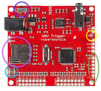
The WAV Trigger is a sound board capable of playing 14 sounds at the same time. It can be powered through the barrel connector on the upper-left in this photo, or through the header circled in green. If the header is used, the “5V” jumper (circled in yellow) must be soldered to bridge the power over. All my installations power the WAV trigger through the header with the 5V jumper soldered.
Part A - Make sure your WAV Trigger is happy. If you can hit the test button (circled in Cyan above), and you hear a sound through the speakers, then your WAV trigger is happy and you can move on to the next part.
With everything plugged in, and the machine turned on, the WAV trigger has a red light that should flash periodically. If you don’t see a red light, make sure you have power & ground to the 6-pin header (circled in green above). 5V should be on pin 3 and GND on pin 1. Also verify that you have a solder bridge on the “5V” jumper (circled in yellow) above.
One you have a flashing red light, verify that the Load/Run switch is in the Run position (circled in Blue above). The Run position is to the right in the photo above.
Verify that you have a proper SD card. The WAV Trigger is particular about what kind of SD cards it likes. Robert has an article about it on his site. I use a SanDisk 16 GB (overkill, but they’re not too expensive). The WAV Trigger only works with samples that are uncompressed, 16-bit, PCM, and 44.1 kHz. There is a zip of test files here — look for the “piano note samples”. When you hit the test button on the WAV Trigger (circled in Cyan above), the LED should go solid while it plays. If it flashes rapidly instead, assume that the problem is with your SD card or the files on it.
Verify that your speakers work (they should be plugged into the 1/8” connector at the top right of the WAV Trigger board). I use computer speakers, some people use sound bars, and there are cables that allow you to plug the WAV trigger into the pinball machine’s built-in amp. Whatever is at the other end of the 1/8” jack, make sure it’s working with another sound source.
If you’ve done all the above, you might have to suspect that the WAV trigger itself is bad. Maybe contact Robertsonics or the board seller for more guidance? If you bought your WAV Trigger with a kit, maybe contact that seller to see if they can exchange your board.
Part B - Configuration. Before you spend a lot of time diagnosing the connection to the Arduino, it’s worthwhile to be sure that the game configuration is squared away. The games I’ve written all have settings to control the sounds, and some even have individual volume controls for music, sound effects, and callouts. Assuming you’ve completed Part A, so you know that the WAV Trigger is happy, it’s time to move onto the configuration.
Use the button behind the coin door to go into the Self-Test, Audit, Settings menu of the game. On games I’ve written past 2022, all the test modes should be narrated “Lamp Test,” “Display Test,” etc. If you hear those callouts when you hit the button behind the coin door, congrats—you’re almost done.
Keep hitting that button until you’re at the sound configuration. Which number is sound configuration? It depends on the game… A lot of games have their settings in the README file on GitHub. For example, Space Battle 2022 has the following settings. The setting at 17 will allow for a combination of built-in and WAV Trigger sounds. You’ll have to dive into the game’s manual to figure out how to set it. Notice also that there are separate volumes for Music, Sound Effects, and Callouts. Those need to be set in order to hear anything.
17:00 - Sound Selector
18:00 - Music Volume
19:00 - Sound Effects Volume
20:00 - Callouts VolumeWhenever the Arduino tries to talk to the WAV Trigger, you should see the LED on the WAV Trigger go solid. If it doesn’t, you might have a hardware communication issue (covered in the next part), or it’s possible that the Arduino isn’t using the correct port. For Rev 1, 2, and 3 boards (formerly known as B/SOS boards), the WAV Trigger had to be on the port called “Serial” in the code. For Rev 4 and up, the port used is now “Serial1”. To check which one your software is using, you need to look at the source files. By the way, if you didn’t load the code onto your Arduino (you bought a pre-configured kit), then you should probably just contact the person who sold you the “ready to go” kit. It should have come with the WAV Trigger working. So the rest of this part is only for people who have loaded their own code, so I’m going to assume some working knowledge of the Arduino compiler.
Does your game have a file called “BSOS_Config.h”?
If so, look for these lines:
//#define USE_WAV_TRIGGER
#define USE_WAV_TRIGGER_1p3
The top line is not active (because it’s preceded with //), so this file is configured to use the WAV Trigger 1.3 software. If your WAV Trigger is not updated to version 1.3, then you’re in for a whole adventure. This page has the new firmware. Updating it can be a chore. If you bought your WAV Trigger after February of 23, supposedly it should have the new firmware. You want the 1.3 because it will lock the background music on. If you can’t update, then put // in front of the “#define USE_WAV_TRIGGER_1p3”, take away the // from the other line and see if that works.
Does your game have a file called “RPU_config.h”?
Look in that file for the #define USE_WAV_TRIGGER_1p3 line and follow the instructions above. It’s the same configuration, just in a different file.
Does your game have a file called “SendOnlyWavTrigger.h”?
If so, scroll down in that file until you see a line that says:
#define WTSerial Serial
If you have a Rev 1, 2, or 3 board, the software is configured properly for you. If you have a Rev4 or above, this software might not be compatible with your board. When the Rev 4 was introduced, the libraries shifted to keep up with the new hardware and “SendOnlyWavTrigger” was phased out for “AudioHandler”. You can attempt to change the “Serial” above to “Serial1”, but I suspect that the libraries won’t align for you to use a Rev 4 (or higher) RPU board with your settings. An exception would be “SpaceBattle2022” which was upgraded to RPU but still uses “SendOnlyWavTrigger”. In that case, you might be able to change this to “Serial1” and have it work.
Does your game have a file called “AudioHandler.h”?
If so, everything should auto-configure in terms of the port, assuming that you have the right #define USE_WAV_TRIGGER_1p3 line set up (as described above). You can scroll down and look for this:
#if defined(RPU_OS_USE_WAV_TRIGGER) || defined(RPU_OS_USE_WAV_TRIGGER_1p3)
#if (RPU_OS_HARDWARE_REV<=3)
#define WTSerial Serial
#else
#define WTSerial Serial1
#endif
That block of code is making sure that you’ve built with at least one of the WAV Trigger flags (regular or version 1.3), and then it defines the Serial port based on the hardware rev.
Part C - Communication with Arduino. The Arduino speaks to the WAV Trigger through the 6-pin header (circled in green above). If you’re running a B/SOS board (Rev 1, 2, or 3), then the Arduino is connected to pins 1-GND, 3-VCC, and 4-TX from Arduino (which is RX on WAV Trigger). For RPU Rev 4 and above, pin 5=RX from Arduino (TX on WAV Trigger) is also used.
Rev 1, 2, and 3 have two serial ports on the lower-left of the board. Both of these ports are the same (wired in parallel). In this picture, I’ve circled the GND, +5, and TX lines in green, red, and blue.

2. Rev 4 and up have three serial ports exposed. Serial 1 is used for the WAV Trigger, and the ports now support an RX line as well. GND, +5, TX, and RX are circled in green, red, blue, and yellow.

3. Rev 102 has the Serial ports down the side of the board. On this photo, Serial 1 is in the upper right corner.

4. Once you’ve identified where the port/pins are located on your RPU board, use a 1x6 cable to connect it to the WAV trigger. Be sure that GND connects to GND, as in the following photos.

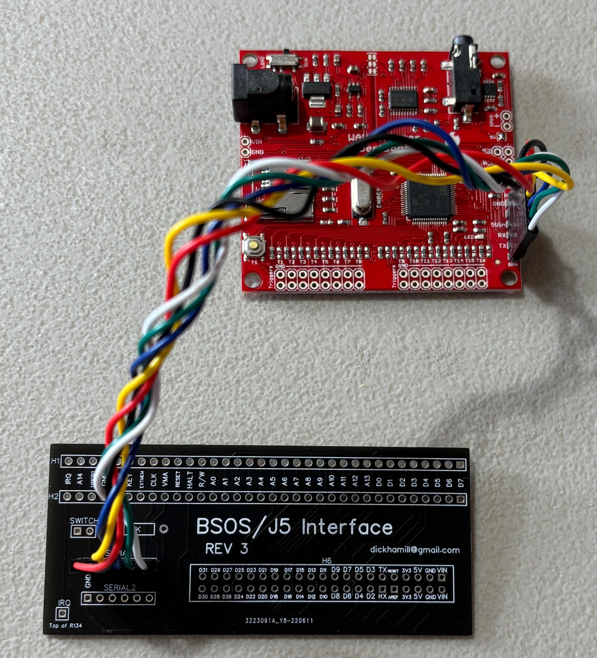

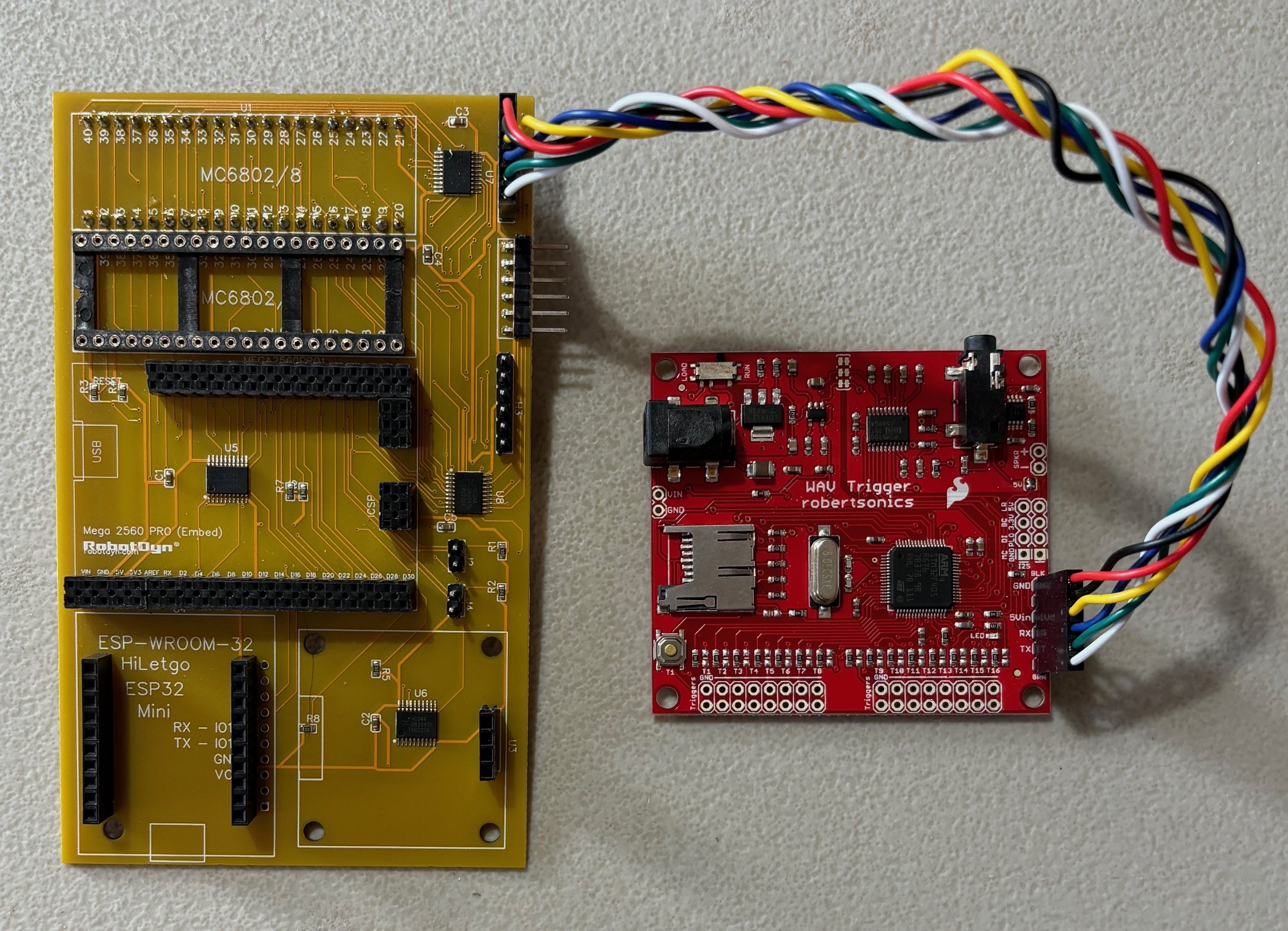
5. If everything is hooked up properly, you will see a flashing red light on the WAV Trigger board when the machine is powered on. This shows you that the WAV Trigger is connected to 5V and GND from the Arduino. Every time the Arduino plays a sound on the WAV Trigger, the LED should turn on solid while the sound effect loads.
If none of the above works, then I’m stumped. Maybe your board is bad? Maybe your cable is bad? Feel free to reach out to me and I can try to help you figure out the issue. It’s easiest to find me on Pinside by posting to this forum topic.