Trident 2022
In 2022, I broke one of my original rules. When I started writing new code for pinball machines, my intention was to leave all the playfield hardware the same as when it was designed. I didn’t replace stand-ups with drop targets, add switches to lanes, or put in flashers. I liked the idea that the game would still act and feel just like it did when it was created. My addition was only a new ruleset and some new sounds.
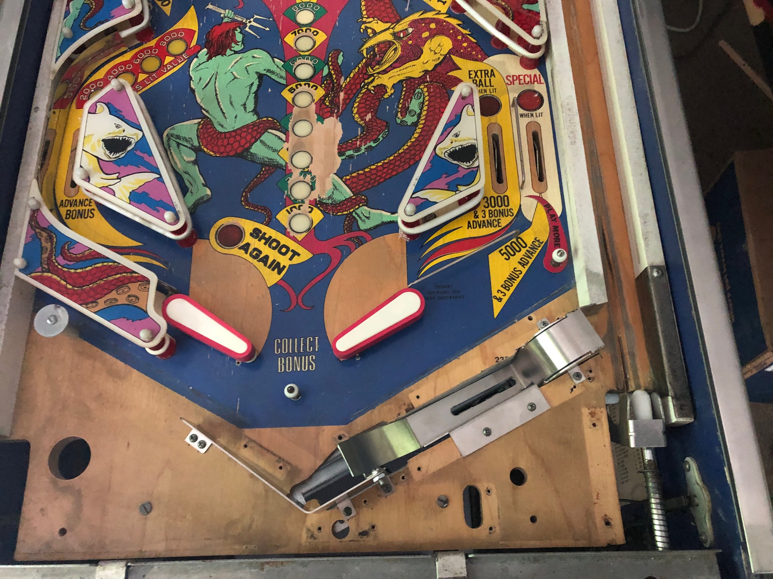
But I really like Trident. It’s not as popular as Stars, although it shares a lot of similarities. With two spinners, upper-left drops, and stand-ups that juice the spinner, it’s easy to draw parallels. What I like more about Trident is that it has a saucer, and a saucer is a great way to start “modes.”
My original rewrite of Trident took advantage of that saucer. If you qualified one or more modes, the saucer would start the action. The more I played Trident, the more I liked it. I began to have a vision of landing the ball in the saucer and kicking off a multiball. So, in 2022, I finally added hardware to a playfield. Specifically, I added a 4-ball trough and an auto-plunger. Now, I like Trident even more. Here are the details.
Parts
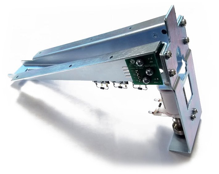
Ball Trough Assembly (4-Ball)
PBL-100-0015-00
$99.95
https://www.pinballlife.com/ball-trough-assembly-4-ball.html
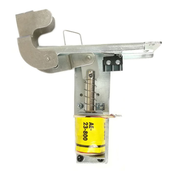
Shooter Lane Auto Kicker Assembly

Upper Ball Trough Assembly (2-piece set)
PBL-100-0002-00
$34.95
https://www.pinballlife.com/upper-ball-trough-assembly-2-piece-set.html
Electronic Components
(Qty 2) 6.7 kOhm 1/4W Resistors
(Qty 2) 68 Ohm 1/2W Resistors
(Qty 2) 1 kOhm 1/4W Resistors
(Qty 2) Diodes (1N914A or 1N4004)
Mechanical Details
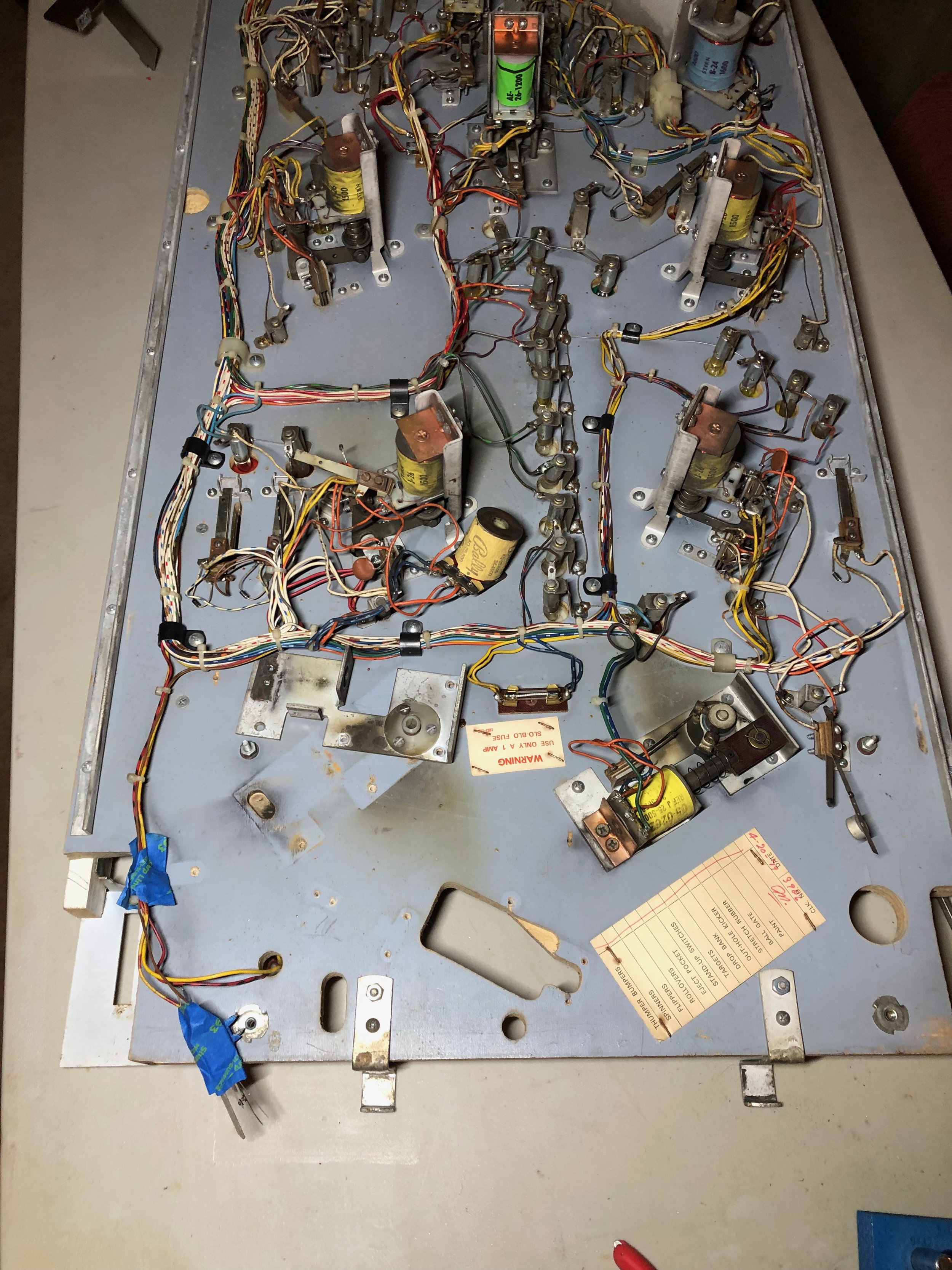
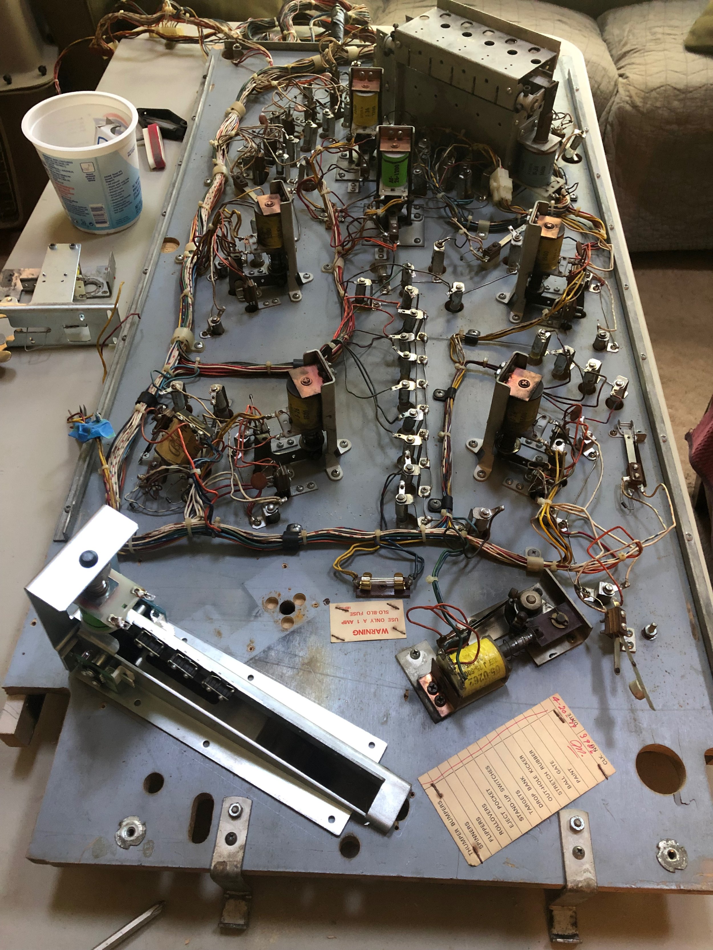
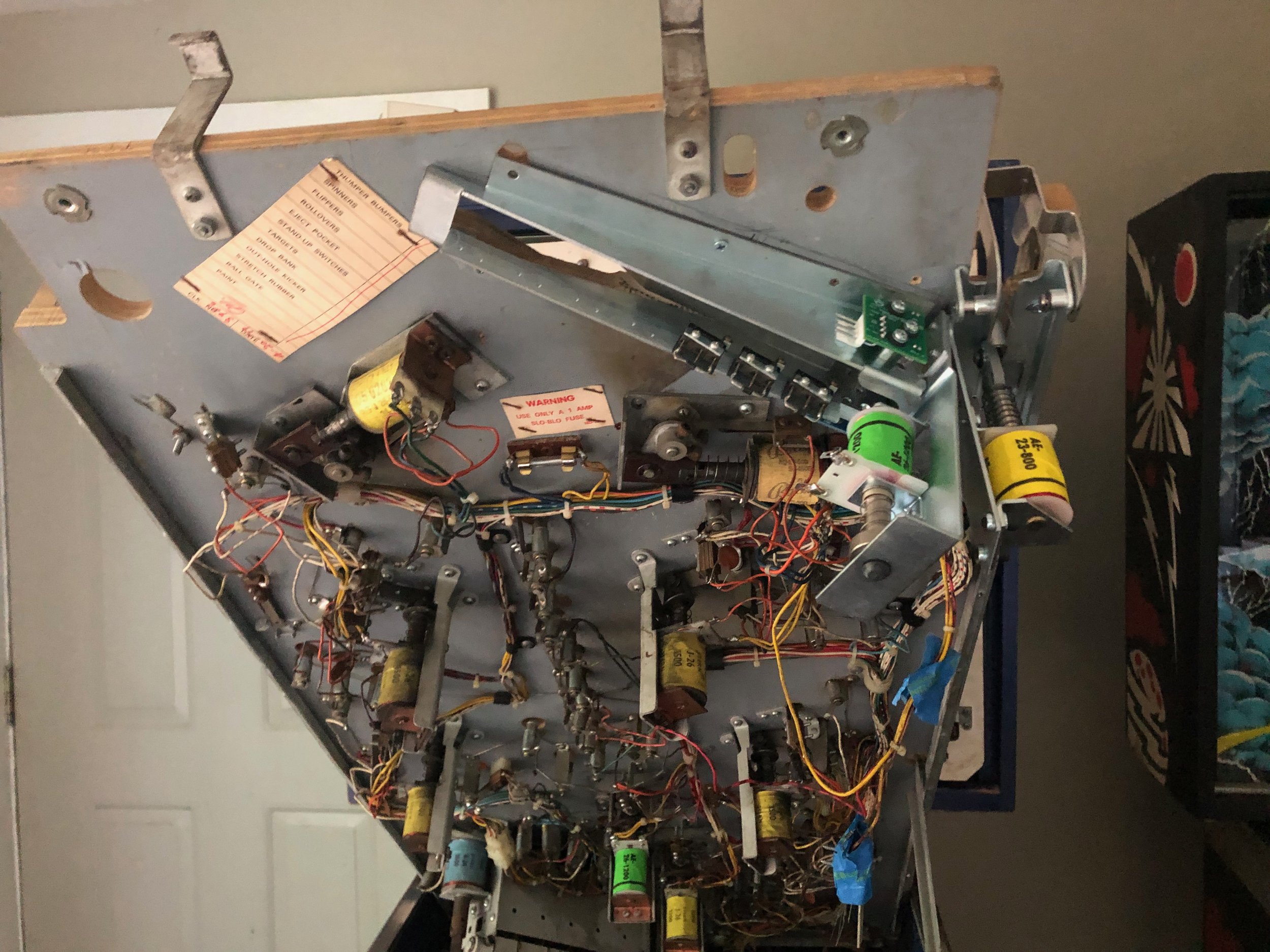
After rotating the right flipper assembly a bit, cutting out a chunk of wood, and shortening a bottom rail, I added a 4-ball trough and an auto-plunger. There were plenty of vacancies on the switch matrix to support the 5 new switches. For the trough kicker, I used the original solenoid assignment. The auto-plunger is attached to one of the driver board's unused "continuous" solenoid channels.
By attaching the "ball 4" position to the original trough switch, and using the original solenoid channel for the trough kicker, the game still plays the original, unmodified code as expected.
With the playfield flipped, the right flipper (now on the left) can be rotated about 50° clockwise. To rotate the bracket, remove the solenoid, arm, and screws, and situate the bracket on the other side of the protruding screw and nut (these belong to the apron holder).
Remove the metal rail from the underside of the playfield (it's under the shooter lane) and cut off about 5" (just enough to fit the auto-plunger).
Cut a rectangular slot in the playfield to fit the new trough (see pictures). I used a reciprocating saw with a wood blade to extend the rectangular slot that already exists.

Mount the trough assembly to the underside of the playfield.
I installed a wooden ramp (end grain, hardwood) to prevent the ball from rolling back into the trough. The new code uses the "jam" sensor to detect rollbacks and clear them, but the old code doesn't know about that and will malfunction if the ball sneaks back in after bouncing off the far rail.

Install the ball guides on the top of the playfield.

Drill new relief holes for the flipper insert screws (50°~60° off from originals).
Cut a slot under the shooter lane for the new shooter lane sensor.

Install the auto-plunger.
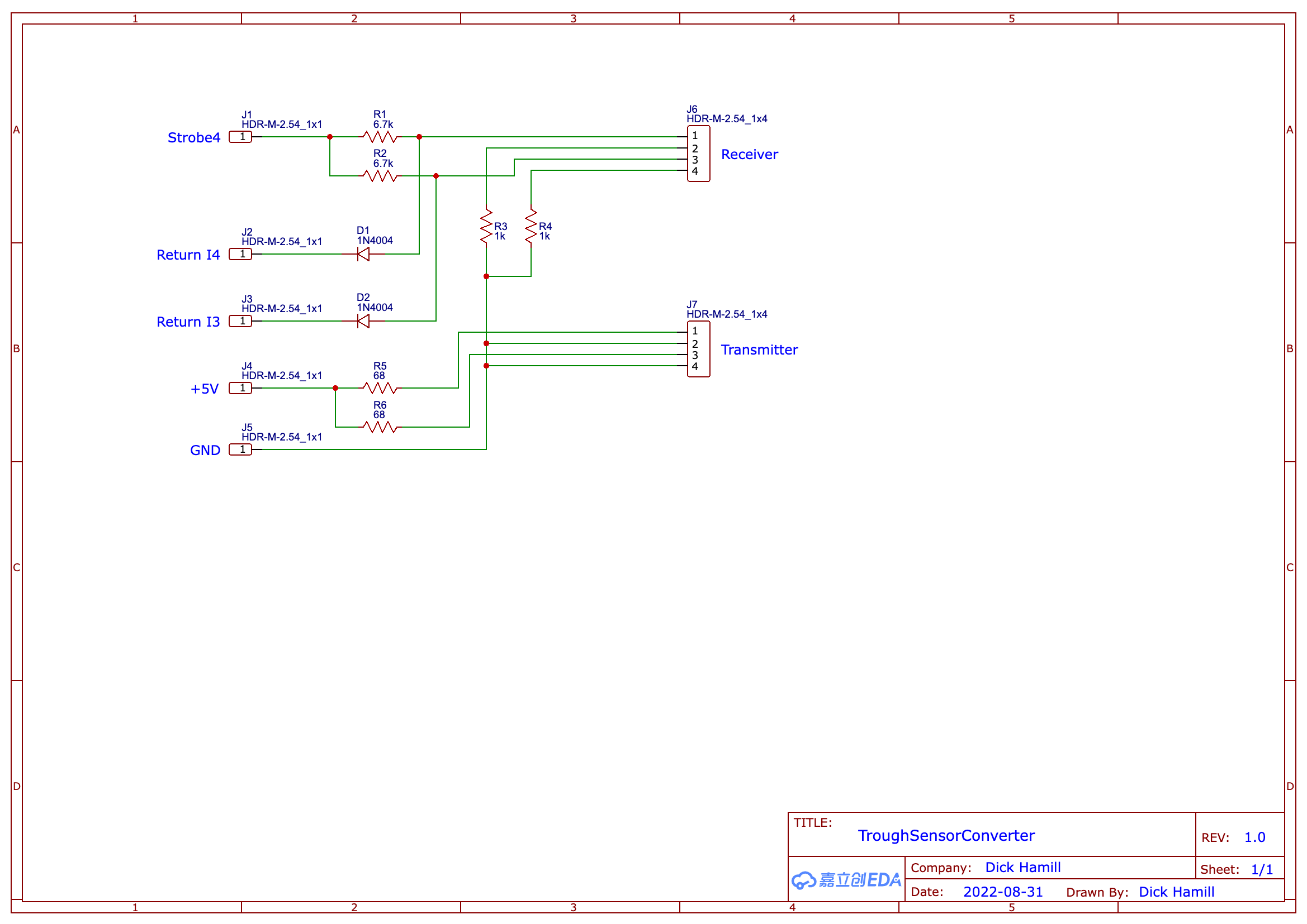
Switch Wiring
The switch matrix on Stern solid state games uses 5 strobe lines going out to banks of 8 switches. After going through a diode and the switch, there are 8 return lines to take the signals back to the MPU. This gives the machine the ability to read 40 switches, but Trident has many open slots in the switch matrix (for our purposes, 34-38 are open). To connect into the matrix, we'll chain off of the strobe of the original outhole switch (number 33) to go to the leading edge of the diodes for each of the new switches (Ball 3, Ball 2, and Shooter Lane). The optical switches will require a special circuit board.
The strobe for the original outhole switch (number 33) is yellow with red. Attach that wire to the leading edge of the diode on the Ball 4 switch. Then, daisy chain that strobe to the leading edge of the diodes on Ball 3, Ball 2, and the Shooter Lane switch. A final daisy chain will go to the board to interface with the optical switches.
The return for the original outhole switch is brown. Attach that to the return contact of the new Ball 4 switch (center contact). The returns for Ball 3, Ball 2, and Shooter Lane will go to other switches on the matrix.
Run a new wire from the return (center contact) of the Ball 3 switch over to the Right Return Lane switch (number 18). Attach this new wire to where the Gray wire returns the switch signal to the MPU (I1).
Run a new wire from the return (center contact) of the Ball 2 switch over to the Left Return Lane switch (number 19). Attach this new wire to where the White/Orange wire returns the switch signal to the MPU (I2).
Run a new wire from the return (center contact) of the Shooter Lane switch over to the Bottom Left Sling switch (number 14). Attach this new wire to where the White/Brown wire returns the switch signal to the MPU (I5).


Optical Interface Board
In order to read the optical switches, the signals from the optical receivers have to be manipulated. This board is simple and requires only resistors and diodes:
(Qty 2) 6.7 kOhm 1/4W Resistors
(Qty 2) 68 Ohm 1/2W Resistors - to current limit the transmitters
(Qty 2) 1 kOhm 1/4W Resistors
(Qty 2) Diodes (1N914A or 1N4004)
To power the transmitter, we'll need +5V and Ground. For those, I ran two wires back to the head of the machine (red & black) and clamped into TP4 (GND) and TP5 (+5V) on the MPU. I'm sure there's a more elegant solution. Please suggest one if you have it. The transmitter LEDs need to be current-limited with resistors. On the trough's transmitter board, it says the LEDs want "100MA MAX EACH." I found that 70mA works well, so I used 68 Ohm resistors between +5 and the + pin of each LED. With 68 Ohms, at 0.073A, the power used by each will be about .36W, so I used 1/2W resistors for each LED. To the transmitter connector, we only need four signals--the two current-limited connections to 5V, and then two connections to ground.
The receiver board will be interfaced into the switch matrix. The receiver sensors act like transistors--if they see the transmitter then they provide a path to ground. We'll use a 6.7 kOhm resistor to connect the strobe to each receiver's positive terminal. This resistor will prevent the receiver from eating the entire strobe, so the physical switches will still see it. Then, the negative terminal of each receiver will have a 1 kOhm resistor between it and ground. Diodes (1N4004 or 1N914A) allow the Return lines I4 and I5 to sense the strobe if the receiver is blocked. In this configuration, the switch will appear "closed" if there's a ball in the way (because the strobe will get through to the return lines), and "open" if there's no ball (because the strobe will be grounded).
I put both of these circuits on the same board (for biasing the transmitter and conditioning the receiver). It's a quick build on a prototype board but might be worth creating a layout for in the future.
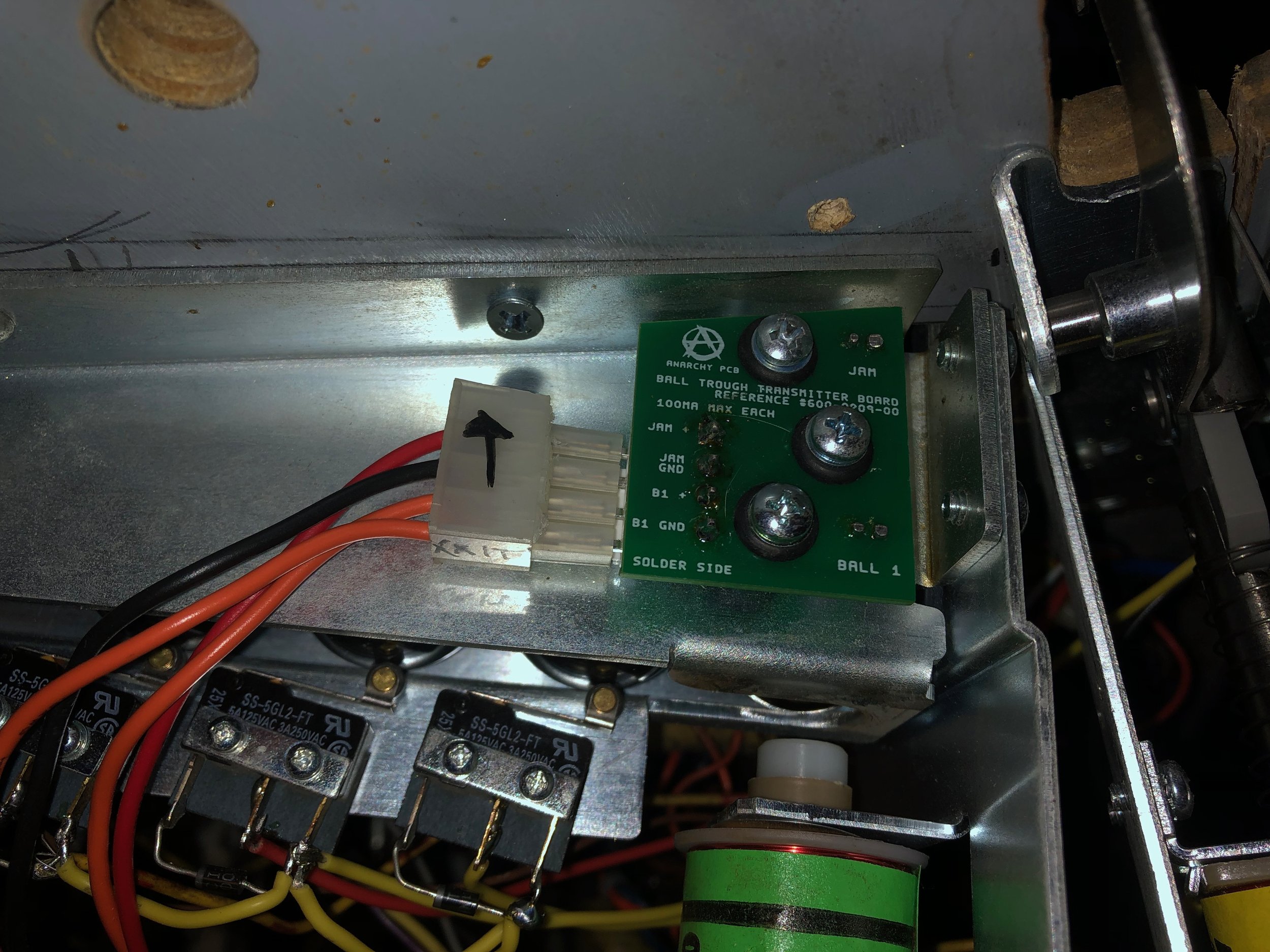
Like the physical switches, the returns for these optical switches need to be wired back into the matrix. The "JAM" sensor return should be connected to the Bottom Right Sling-Shot I4 (White/Green), and "Ball 1" to the Top Left Sling-Shot I3 (White/Black).
The connectors of the transmitter and receiver boards appear to be friction 4-pin Molex at 4mm spacing? If anyone knows where to source these, please comment. I'm using a connector that I cut off an old power supply that I wasn't using. My board is just hanging by the wires. It should be mounted to the playfield with offsets.
Solenoid Wiring
The wiring for the trough solenoid is the same as the original. The power goes to the terminal with the banded side of the diode, and the ground wire goes to the other terminal.
To wire up the auto-plunger, jumper the power from the trough solenoid over to the auto-plunger solenoid. Again, power goes to the terminal with the banded side of the diode. For ground, we run a new wire up to the head. This new wire will connect to one of the continuous solenoids on J5 pin 7.
