Parts List for the ALB
Links on this page are working as of 2/27/2025 — if you find a broken link let me know
ALB PCB
Printed Circuit Board (PCB)
I usually get my PCBs from JLCPCB or PCBWay. To order from one of these sites, you upload this Gerber file. Depending on the use, you may only have to populate a couple of the areas on the ALB PCB. The following sections will list the parts needed for these areas:
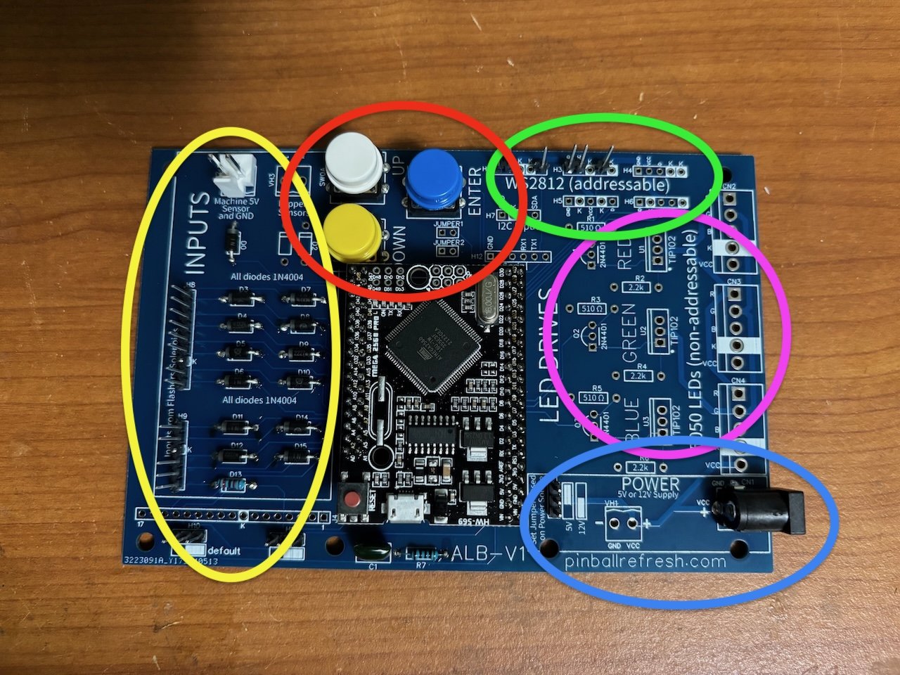
1) Power - shown with a Blue circle in the image. You can power the ALB through either a barrel connector or a 2-pin (0.156”) header. Power is either 5V or 12V, and you have to set a jumper (H1) based on the input voltage. It’s mandatory to provide power. If you use a barrel connector, you can get an inexpensive 12V or 5V adapter to drive your lamps.
2) Arduino - not circled, but it’s the Black Microcontroller mounted in the center of the PCB in the image. This is an Arduino MEGA 2560 Pro. You have to get the 2560 Pro model specifically to get the right pin layout. I usually buy them from Amazon, but you can sometimes find better deals elsewhere.
3) WS2811 or WS2812 addressable LED Strips Output - shown in the green circle in the image. There are five output jacks for WS2811 or WS2812. Any of these ports can drive strips for toppers, speakers, back box, under cabinet, or stadium lamps. There are multiple jacks here to just to make things more modular. You may not need to populate these jacks if you’re only running non-addressable strip lights. If you do populate these headers, I recommend longer pins for the job. But any 0.100” male connectors will do the job (5 pins per port). A good locking connector might be perfect, but I don’t have a part number on that. THIS SECTION IS OPTIONAL and only populated if you’re driving addressable LED strips.
4) Non-addressable (5050) strip drivers - shown in the purple circle. This section requires transistors, resistors, and connectors. Once populated, you can drive non-addressable strip lights (the kind with 3 separate channels for Red, Green, and Blue), or you can use the three channels to drive 12V LED GI bulbs, which is great for non-animated back boxes. With a sensor hooked to the Flipper relay, it’s simple to make a back box that dims during gameplay. The full circuit requires 3x TIP 102s, 3x 2N4401s, 3x 510 Ohm, and 3x 2.2 kOhm resistors and then 3x of the 1x5 0.156” Molex male headers. THIS SECTION IS OPTIONAL and only populated if you’re driving non-addressable LED strips or GI LEDs.
5) Input section - shown in the yellow circle. This section can sense Solenoid state, flipper relays, if the machine is on (5V sensor), and has a port that allows the ALB to act as a Bally/Stern lamp board. To populate this section, you just need as many 1N4007 diodes as you have inputs. There are some resistors and a capacitor if you’re making a replacement Bally/Stern lamp board, and then a bunch of 0.100” and 0.156” header pins for these inputs. THIS SECTION IS OPTIONAL and only used if you need to get information about the pinball machine’s hardware state. If you’re running animations based on i2c control from an RPU board, you might leave this section unpopulated.
6) Buttons - circled in red. I use these buttons to set the brightness of animations and scenes on the board, but these buttons might be superfluous if you’re doing brightness through the operator menus on the pinball machine. THIS SECTION IS OPTIONAL unless you like buttons, which I do.
List
Required - Power
Qty 1, DC Barrel Connector Part# PRT-00119
(OR)
Qty 1, Molex 2pin Male Header (0.156") Part# 26-60-4020
Power Supply (you can calculate how many amps you need or just read the specs of whatever LEDs you’re driving. I usually allow for 6mA per LED, so a 5A will comfortably drive 80 addressable LEDs at full blast). Or maybe you can pull power from the pinball machine? I don’t recommend overloading a pinball machine’s power supply though. I’d rather hook up a switched AC jack in there and run another power supply.
(OR)
Required - Arduino
Qty 1, Arduino MEGA 2560 Pro (with CH340G)
(optional) 0.100” F Header Pins for Arduino (or you can just solder the Arduino into the PCB)
(OR)
(optional) or if you want really nice headers, consider these from 3M.
Qty 1, 2x5 for Arduino 3M Female Header (2x5) Part# 929852-01-05-RA
Qty 2, 2x16 for Arduino 3M Female Header (2x16) Part# 929852-01-16-RA
Optional - Header Pins Addressable LEDs
Qty 5, 1x5 0.100” M Header Pins
Qty 5, 1x5 0.100” F Headers and F Pins - I like this kit, which has plenty, but in a strict Molex sense, these KK 2695 housings are appropriate. If you go with the Molex housings for you cabling, you’ll need crimp terminals. I can’t find them on Mouser at the moment, but you can get them at Marco or Jameco has a good price if you’re buying other stuff too.
Good wire for addressable strips.
I usually get reels of addressable LEDs from Amazon, either as WS2811 or WS2812 (look for the pixel density and waterproofness that you want).
Optional - Non-addressable (5050) Strip Drivers (there are simpler MOSFET ways to do the following, but I chose parts that are commonly in a pinball person’s kit)
Qty 3, TIP 102 Transistors
Qty 3, 2N4401 Transistors
Qty 3, 510 Ohm 1/4W resistor
Qty 3, 2.2 kOhm 1/4 resistor
Qty 3, 1x5 0.156" Molex Header (26-60-4050)
Then some housings and crimp terminals to plug into those headers:
Qty 3, 1x5 0.156” Housing (26-03-3051)
Qty 12, Crimp Terminals
RGB (5050) Strip Lights (note that all your pixels will be set to the SAME color with these)
I usually get a reel from Amazon - there are tons of options for 5050 strips, just pick a voltage/waterproofness/density/brightness you want.
You can also use this section to drive 12V GI bulbs.
Optional - Input Section (if you want to sense a pinball machines solenoids, flashers, flippers, or on/off state)
1N4004 Diodes (quantity depends on how many lines you want to sense)
Qty 1, 1x6 0.100” M Header pins (for small input jack)
Qty 1, 1x9 0.100” M Header pins (for larger input jack)
Qty 1, 1x17 0.100” M Header pins (if you’re operating the ALB as a replacement lamp board for Bally/Stern early solid state machines)
Female Connectors to plug into Solenoid/Flasher sensing ports
Qty 1, 1x6 0.100” F Connector housing
Qty 1, 1x9 0.100” F Connector housing
Female Connectors to plug into Flipper / Power sensing ports
Qty 2, 2-pin F 0.156” Molex #26-03-3021
Qty 4, Crimp Terminals for those connector bodies
If you want to sense particular lamps on a Williams game, like I did on The Getaway, you’ll need some parts:
Qty 1, 22k 1/4W Resistor (replaces diode in D13 location)
Qty 1, 5.1k 1/4 Resistor (R7)
Qty 1, 47nF Capacitor (C1)
Optional - Buttons
Qty 3, Buttons - there are two overlapping button footprints, so a variety of momentary buttons should fit.
Optional - Other Parts
0.100” M Headers for i2c, Serial, power selector, and other jumpers
Aligator Clips (I cut these in half to clip to solenoid tabs to sense them)