ALB for The Getaway
I was lucky enough to host a Williams “The Getaway: High Speed II” for a chunk of time. While it was here, I swapped the playfield, did some minor repairs, and added some lighting accessories. Everything I added is run through the Accessory Lamp Board (ALB) . There’s a parts list for this build at the bottom of this page.
Animated Speaker Lamps
Animated Under-cabinet Lamps
Speaker Lamps
For the speakers on The Getaway, I 3D printed two rings (they’re different sizes on these games). The rings allowed me to mount LED strips around the circumference. The right speaker has 6 pixels and the left speaker has 8. Each “pixel” is made up of three LEDs, so they’re plenty bright.
Under-Cabinet Lamps
For the under-cabinet lamps on The Getaway, I wanted to be able to do left/right animations (like a police car’s lights strobing blue and red) and also reproduce the circular effect of the Mars lamp on the top of the cabinet. I’ve done two kits for different machines—on the first one I did lighting strips on the front back and either side. On the second machine, I only put the lamps on the sides. Honestly, there wasn’t a noticeable difference so when I do another machine like this I’ll just do the side rails.
Sensors

H8 Harness

H9 Harness
The ALB can sense up to 13 solenoids/flashers, but I also wanted to be able to sense the state of the Red/Yellow/Green traffic signal lamps. So I used 4 of the sensor input for lamps (1 column strobe, and 3 for the rows). That left me 9 channels for inputs. Here’s my full list of sensors:
Connector H8 (pins from top to bottom)
1: A12 (D7) - Q42: Right Bank Flasher J126Pin1
2: A11 (D3) - Q22: Mars Lamp J123Pin4
3: A10 (D8) - Q36: Freeride Flasher J126Pin4
4: A9 (D4) - Q38: Left Slingshot Flasher J126Pin3
5: A8 (D9) - Q28: Left Ramp Flasher J126Pin5
6: A7 (D5) - Q40: Supercharger Flasher J126Pin2
7: KEY
8: A6 (D10) - Q30: Left Bank Flasher J126Pin6
9: A5 (D6) - Q32: Right Slingshot Flasher J126Pin8
Connector H9 (pins from top to bottom)
1: A4 (D11) - Q86: Stop Light Green
2: A3 (D14) - Q87: Stop Light Yellow
3: Key
4: A2 (D12) - Q88: Stop Light Red
5: A1 (D15) - n/a
6: A0 (D13)* - Q92 (lamp column 7) to Pin D2 on Arduino for interrupt
Machine 5V Sensor and GND (upper left)
The pin on the left will connect to any ground (strap, or the TP5 Gnd pin on the driver board)
The pin on the right will connect to 5V (TP2 Test point on the driver board) so the ALB knows when the machine is on

Speakers - plugged into H3
Under-cab - plugged into H2

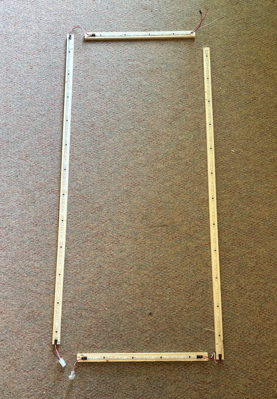
Long rails are 47 3/4”
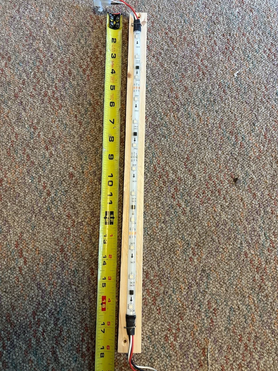
Short rails are 18”
For these two connectors I just cut alligator-clip leads in half and crimped them into a Female connector body. These will clip onto the transistors (the Q numbers listed above).
* It’s important to note that the D13 location will not have a diode, but will instead have a 22k 1/4W resistor installed. This is to sense the lamp column 7 state.
This board will populate C1 and R7. Those components are only used when lamps are being sensed.
There are two jumpers in the lower-left corner of the ALB (H10 and H11). The H10 jumper has to be between pins 2&3 (the right pins). You can do this with a 3-pin header and a jumper cap, or just solder wire connecting pins 2&3 of H10. H11 isn’t used.
Explanation of Stop Light Sensors - When the lamp column (Q95) transistor fires, Q86, Q87, and Q88 will be on or off to show the lights on the playfield. The ALB triggers an interrupt on Q92 (through the H10 jumper, R7, C1, and the resistor installed in the D13 location. When that interrupt happens, the ALB reads Q86, Q87, and Q88 through the three pins on connector 9. With a little code debouncing, we know if the stoplight lamps are lit.
Parts List
First, a brief explanation of Strip LED options. I recommend 12V strips for this, and I generally go for WS2811. For the speakers, you want something with a pretty good pixel density. The code currently expects 6 pixels for the right speaker and 8 for the left, although it’s not that difficult to change the code so if you’re adventurous you could use higher-density strips. For the rails, the first time I build this mod I went with very low-density (10 pixels per meter with 3 LEDs per pixel). Those are the ones pictured in the rails above. The nice thing is that they’re splash proof, but that doesn’t really matter in my opinion. The rubber coating might give you a bit more durability?
I would just by these 60 pixel / m strips and use them for both the speakers and under-cab rails. This is the rubber-coated version. I haven’t tried rubber-coated around the speakers. It seems like they wouldn’t bend enough?
A single reel of LEDs is 5m (16+ feet), which is plenty for this whole project and currently costs less than $25 USD.
LED Strips WS2811, 5m, 60 pixels/m
3D printed speaker brackets, LEFT and RIGHT (STL files)
ALB Board (every section except the 5050 LEDs, or section 4)
The Female headers and pins for the connectors are listed on the ALB parts page. Pay attention to the keying of H2, H3, H8, and H9 - they’re all different. Also be sure to give yourself long enough leads to the Alligator clips, speakers, and under-cab lamps. I’ve made my under-cab harness* too short several times so when you fold down the head it pulls out.
*Note on the long lead — if your wire is more than a few feet to any of the LED strip lights, you might get interference in the data (which appears as flickering LEDs). The way to eliminate this is to put a 470 Ohm resistor inline with the data line (marked as “D” on H2) as close to the first pixel as possible. Like, when you put a pigtail on the input for the under-cab light strip, put a 470 Ohm resistor inline with that.
Code
I put all the code for this mod on GitHub here. To upload it to the Arduino, you can follow the steps here. There’s no RPU_Config.h to modify for this project, but the other steps on that page should be appropriate.
In your Arduino IDE, you’ll have to install the NeoPixel library to build this code.
Click on Sketch > Include Library > Manage Libraries…
In the search box, type “neopixel” and install “Adafruit NeoPixel by Adafruit”
Installation
With most pinball machines, I like to mount the ALB in the head. For The Getaway, I put it on the right side. The harnesses need to clip onto the appropriate transistors. The speaker lamps and under-cab lamps will plug into this as well. I powered the ALB with an additional 12V power supply (linked on the ALB parts page).
When you’re done, you should have things plugged into:
The barrel connector (12V power)
H2 (under-cab lamps)
H3 (speaker lamps)
H8 (solenoid and flasher sensors)
H9 (lamp matrix sensors)
Let me know how it goes and post a video of your results!
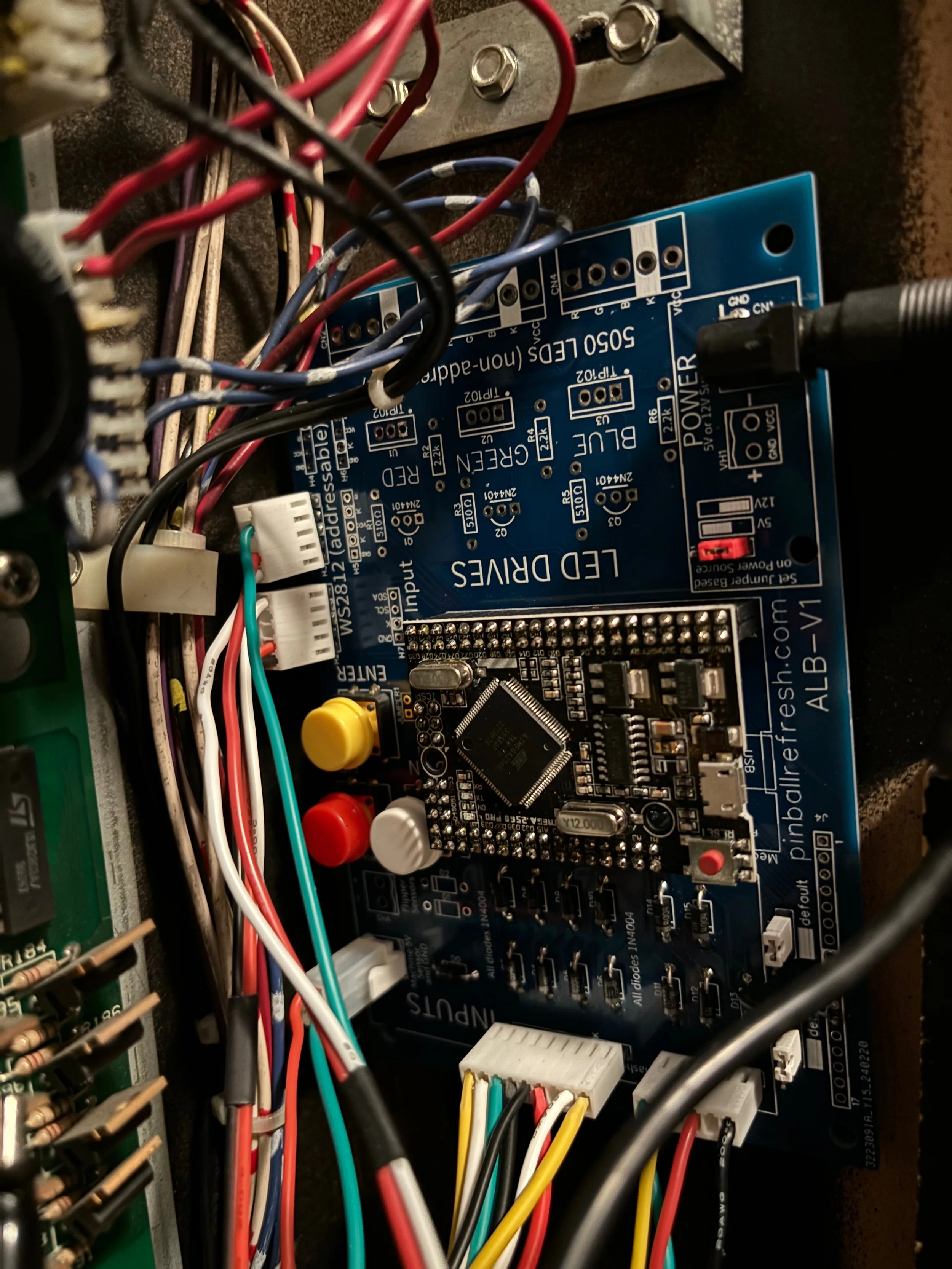
ALB installed (this version had the barrel connector on the side, which was terrible).
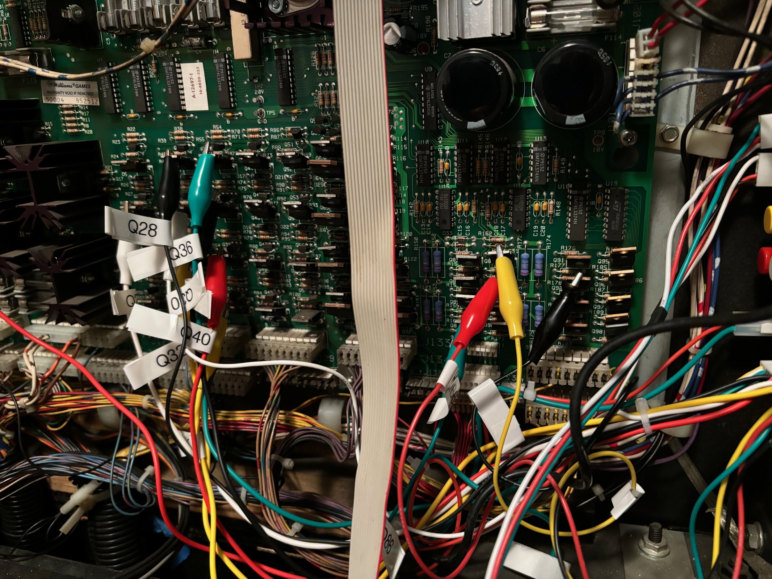
Alligator clips on transistors.

Speaker lamps.